18.02.2015
Schematic Symbol Properties for DxDesigner
As we’ve covered in other posts on schematic symbols, one of the key goals of a librarian is to maintain consistency, both in terms of visual appearance of a symbol, and parity with a manufacturer’s data sheet. Establishing a set of standards which all schematic symbols must abide by allows for more timely part identification, and cleaner, easier to read schematics. With that in mind, let’s take a look at display settings for schematic symbols within Optimum’s library.
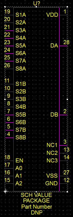
Base Symbol: adg1407-dil28.1 (dual inline IC, 28 pin)
Grid
Maintaining a consistent grid is necessary for ensuring that labeling is consistently spaced around the part, allowing for easier reading.

Default grid for moving pins and adjusting body size is 0.1.
Default grid for moving pin numbering and labeling is 0.050.
Labeling
Pins
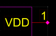
Default pin length, .2
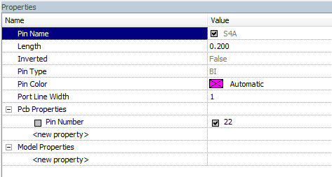
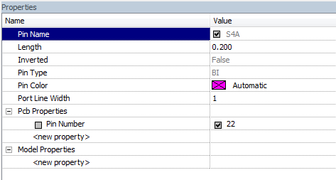
Pin Properties
Pin Numbers

Size 15 Arial, orientation is lower opposite side of the symbol. IE, left hand pins have lower right orientation. Pin numbers should be above the pin. Pin numbering .1 to the outside of symbol body.
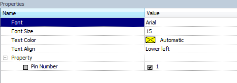
Pin Numbering Properties
Pin Labels
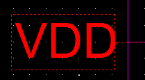
Size 15 arial, orientation is middle same side of the symbol. IE left hand pins have middle left orientation. Pin labels should be .050 to the interior of symbol body.
Always centered, expand part relative to labeling for visual consistency.
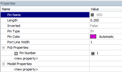
Pin Labeling Properties
Part Labeling
Top of Part

Ref Des: Arial size 15, middle center orientation
Bottom of Part

SCH VALUE: Size 15 arial, orientation: middle center
PACKAGE: Size 15 Arial, orientation: middle center
Part Number: Size 15 Arial, orientation: middle center
DNP: Size 15 Arial, orientation: middle center
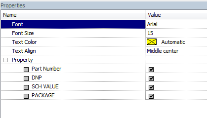
Part Labeling Properties (Top and Bottom)


