03.03.2021
Fixturing vs. Paneling in SMT


When a PCB is thin, small, oddly shaped, or requires SMT components near its edges, chances are these kinds of boards won’t fit properly into your pick-and-place, reflow oven, or automated inspection machines. That's why many manufacturing engineers use fixtures to secure and support these kinds of PCBs. But the cost of fixtures can add up. A new, custom fixture must ordered for every new design, and there’s usually a 3-4 day wait for it arrive. It ends up costing more for the customer, without adding significant value to the end product.
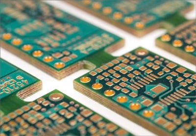
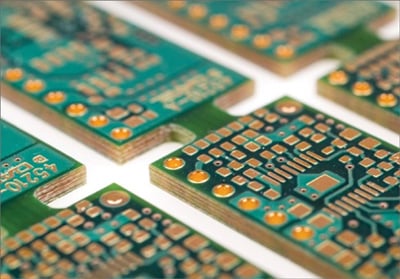
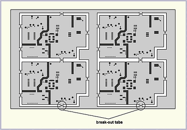
To address these costs, manufacturing engineers may either “panel up” or add tooling strips. Paneling up refers to the process of framing an oddly shaped board—or multiple small boards—in extra fab material, thus creating a fabricated fixture that can be removed after assembly and reflow. Because panels can be directly requested from the fabrication shop, paneling saves time and reduces cost. Tooling strips are commonly used when components sit close to the edge of a PCB and a buffer is needed during the assembly process. This strips are usually scored and easily broken off after the SMT placement and reflow.

In some cases, however, using fixtures is unavoidable. Some designs require smooth edges, and break-out tabs on paneled PCBs may leave small bumps at the edges of the board. Paneling added to the edges of a board (usually with components near the edges) may leave residue where the panel was scored and then broken off. Also, paneling may not work on thinner boards, which require extra support in the pick-and-place machine.
Overall, a small to mid-size PCB shop will use fixtures about 20% of the time, and panel up on about 55% of its boards. Paneling has become popular in recent years due to the widespread use of smaller PCBs. In order to save time and reduce cost, use fixtures in SMT manufacturing only when necessary.
This post originally appeared on the DigiSource Blog


