22.04.2015
How to Place Breakaway Rails in a PCB Design

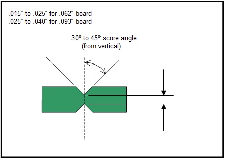
Designers must be aware that the customer-supplied board outline shape isn’t always necessarily the shape that is to be delivered to the fabrication and assembly house for manufacturing. PCB’s must have two parallel sides (preferably the two longest sides) for processing them through the assembly equipment (conveyor transport).

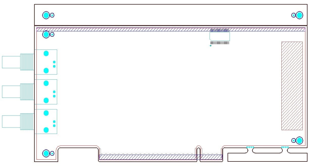
Figure 1: Mechanical Definition

Figure 2: Mousebits
Breakaway rails that are added only for increasing component–to-board-edge clearances are to be at least .500". These rails should also include fiducials and a .125" non-plated tooling hole in each corner (see Figure 1). The component at the top edge of the board may violate the component keep-out area shown because the added v-groove breakaway rail allows the board to be fabricated and assembled with proper clearances. Please note that if the board will be part of a sub-panel assembly, rails are not necessary, since the sub-panel will have the rails. Rails take up material and thus add cost.

Figure 3: Breakaway Rails


![Download Optimum's Designer Handbook! [PDF format]](https://no-cache.hubspot.com/cta/default/317720/240d1413-c945-4cb8-a546-a84937b16039.png)