17.12.2014
PCB Library Management Part Three: Symbol Naming


Symbols are the second major portion of any PCB library. Electrical symbols show the connection between parts, and are utilized on schematics to depict the functionality of circuits. Just as the goal of the naming convention for footprints is quick and easy identification, symbols should be named and organized for rapid access.
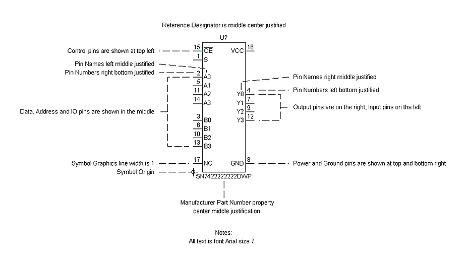
Typical IC Symbol Structure

Name Prefixes
Symbol prefixes, when used, should be self-explanatory as to what part type the component symbol represents. It should be your goal to use common, industry-standard abbreviations. For example, plg = plug, cap = capacitor, etc.
Manufacturer Part Number Qualifiers
Many symbols simply use the MPN as the symbol name qualifier. This convention is useful for ICs, but can also be used for other symbols when deemed appropriate.
IC symbol naming is in the form of Base Manufacturer Part Number – Package.
For example, symbol named lt1618-dfn10h. This symbol features the Linear Technology part number lt1618 dual flat no lead 10 pin heatsink pad.
Multiple Symbol Qualifiers
Pin group qualifiers (suffixes), are used to name the separate symbols used in a device according to various pin groups. For example, -gnd, -cfg, -bnk2.
Part Type Qualifiers
Outside of part type prefixes, many symbols can also use other descriptive part type qualifiers in their naming conventions. Most of these qualifiers are readily identifiable as industry standard abbreviations. For example, var = variable, pol = polarized. A list of all part type qualifiers utilized by Optimum internally is available at the bottom of this post.
Package Type Qualifiers
IC symbols may contain a package type suffix where devices are available in different package pinouts. For example, dil = dual in line, qfn = quad flat no lead. Some generic style IC symbols will not require this suffix. For example, reg-iioa = regulator with 2 input, an output, and an adjust pin in any package.
Pin Number Qualifiers in Symbol Names
Symbols have pin number information included in the symbol name. This is Optimum’s preferred method of making symbols as generic as possible without needing additional “side” files or attributes to manipulate pin orders and numbers.
For example, the symbol “reg-iioa.1” can be used for any regulator that has the pinout of 2 inputs, one output, and one adjust pin. “mosfet-n-gdsss” can be used for any n channel mosfet with 1 gate pin, 1 drain pin, and 3 source pins.
This method enables the use of one symbol for many different devices. This naming convention may be used for any part type having a maximum of 8 pins. See below for a list of abbreviations utilized in the Optimum library.


