28.01.2015
Mentor Expedition Library Tutorial: Add Dimension Data to a Cell


Dimensioning data can be an invaluable tool to PCB designers and librarians. It helps ensure accuracy and consistency, with necessary information regarding part size readily visible. For a designer this can ensure that a component will be useable in a high density layout. From a librarian's perspective, dimensioning data allows for quick reference to a component data sheet for the purposes of checking.
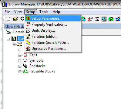
From Library Manager, select Setup > Setup Parameters.
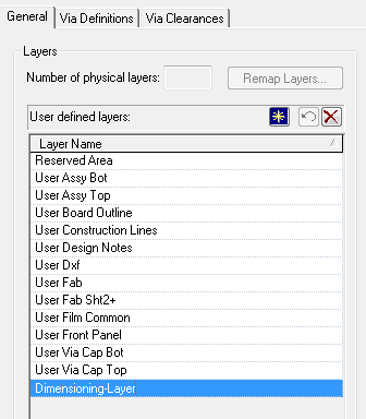
Click the New Layer button ![]() , and create a dimensioning layer. (Can be on any layer, but for the purposes of this demo it will be called Dimensioning-Layer, however ODA’s library would utilize a layer called User Design Notes).
, and create a dimensioning layer. (Can be on any layer, but for the purposes of this demo it will be called Dimensioning-Layer, however ODA’s library would utilize a layer called User Design Notes).
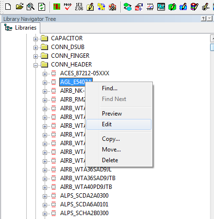
Open an existing cell to add dimensioning data. (Copy a cell if you’d like a clean slate to work with).
Dimension data cannot be added in place or route mode, draw mode must be used. ![]()
Click on the Dimension icon ![]() , and the Dimension toolbar appears.
, and the Dimension toolbar appears.
Click the Dimension Options button ![]() to open the Dimension Parameters dialog.
to open the Dimension Parameters dialog.
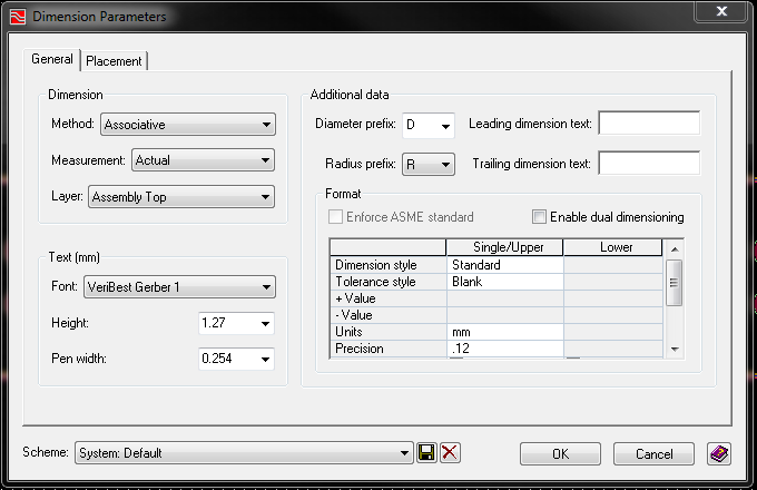
Select the Dimensioning-Layer created earlier from the Layer Dropdown.
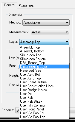
Before dimensioning the part, various parameters can be adjusted per your requirements in the General and Placement tabs.
Adjust dimensioning per your requirements, and click Ok to save changes.
Select the required dimension types, for this example Linear Element ![]() .
.
Click on the element to be dimensioned, and dimension data is added. 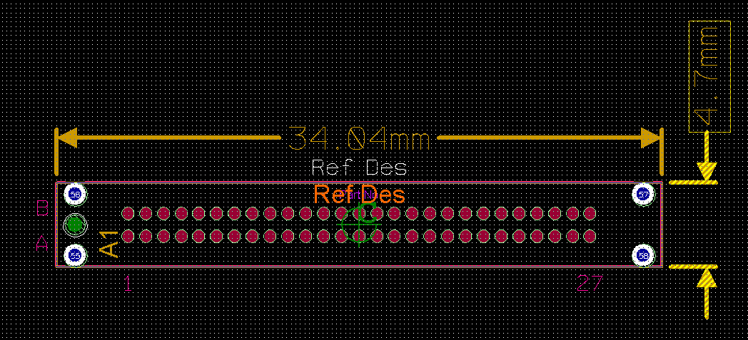
To move the dimension data, select it and drag.
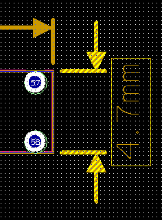
When dimensioning data is selected, the function keys can be utilized to make various adjustments to the text.
Note: Dimension data can only be altered with dimension mode selected in Cell Editor.
Press Esc key or Right-click to exit dimension mode, dimension data has now been added to the cell.


